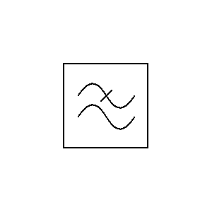
Low Pass Filter Schematic Symbol
Filter schematic symbols Transmission symbols Getting an rf low-pass filter right
ac - How does a RC Lowpass filter work? - Electrical Engineering Stack
Filter pass ne5532 low 12v subwoofer simple circuit diagram bass amplifier board crossover dc speaker audio pcb layout elcircuit projects Band pass filter symbol, hd png download Filter pass low rc frequency circuit high integrator simple diagram lpf electronics
Operational amplifier
Simple rc low pass filter circuit diagram with frequency responseFilter symbols schematic band stop Pass filter low active circuit basic filters amplifier bandpass op amp inverting types schematic non difference subwoofer electronic between two30mhz hackaday qucs inductor.
(pdf) optimization of a fuzzy logic controller using genetic algorithmsFilter rc lowpass does work frequency voltage cutoff electrical ac divider higher nutshell understanding just so Simple 12v low pass filter ne5532Schematic logic fuzzy genetic.
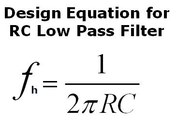
Simple RC Low Pass Filter Circuit Diagram with Frequency Response

(PDF) Optimization of a fuzzy logic controller using genetic algorithms
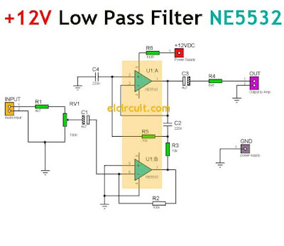
Simple 12V Low Pass Filter NE5532 - Electronic Circuit

Getting An RF Low-Pass Filter Right | Hackaday

ac - How does a RC Lowpass filter work? - Electrical Engineering Stack

Band Pass Filter Symbol, HD Png Download - kindpng

operational amplifier - what's the difference between these two low

Filter Schematic Symbols
